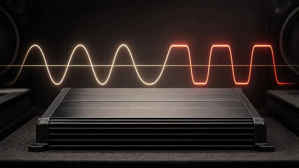
Audio clipping occurs when a signal-processing or amplifier stage is asked to produce an output beyond the range it can reproduce linearly. The output stops following the input at part of the waveform, creating distortion and additional frequency content.
Clipping can begin in a source, processor, line-output converter, or power amplifier. Finding distortion at a speaker does not by itself identify which stage created it.
What the waveform description means
In an ideal linear stage, increasing the input produces a proportionally larger version of the same waveform. Every real device has limits. When the requested output meets one of those limits, further input no longer produces the expected output excursion.
On a steady test waveform, this may appear as rounded, compressed, or flattened peaks. Real music is more complex, and limiting or protection may alter the waveform without producing a textbook flat top.
The Analog Devices amplifier overview discusses output limits, efficiency, distortion, and filtering as properties of an amplifier implementation. Those limits are not determined by the class label alone.
Where clipping can begin
| Stage | Example reason it may reach a limit | Evidence that helps | What that evidence does not prove |
|---|---|---|---|
| Source or head unit | Internal output or processing runs out of range | Measured distortion begins at the source output as level rises | That every source behaves the same at the same display number |
| Factory processing or LOC | Summing, conversion, gain, or equalization overloads a stage | Clean input but distorted output at that device | That the power amplifier caused the original distortion |
| DSP | Input, internal, or output level exceeds the processor’s available range | Channel metering plus input/output measurement | That every clip indicator observes every internal point |
| Power amplifier | Requested output exceeds available voltage, current, thermal, or protection boundary | Suitable measurement at the amplifier output under defined conditions | That the speaker load and installation are safe |
| Recorded program | Distortion is already in the media | The same artifact appears through another known-clean reproduction path | That downstream equipment cannot add more distortion |
The correct diagnostic direction is from upstream to downstream. Replacing a power amplifier cannot remove clipping that already exists at its input.
Gain is not a power control
An amplifier gain or input-sensitivity control establishes how much input voltage is needed to reach a given output. Turning it higher does not increase the amplifier’s fundamental output capability. It can make the amplifier reach its limit with a lower source level and can reduce usable control range.
Equalization can also consume headroom. Boosting a frequency region asks the relevant stage for more output in that region. Whether this causes clipping depends on the signal, gain structure, device limits, supply, load, and settings.
This article deliberately does not provide a universal gain position or a by-ear setup method. A valid procedure must be specific to the equipment and measurement method.
Is clipping always audible?
No. Audibility varies with severity, duration, frequency content, masking, listening level, driver behavior, and the listener. A system may sound harsh, compressed, or obviously distorted, but those symptoms can also have other causes.
Likewise, an illuminated clip indicator is product-specific evidence. Its detection point, threshold, timing, and monitored channel should be confirmed in that product’s documentation. No light does not universally prove that every upstream and downstream stage is clean.
Clipping and speaker damage
Clipping is undesirable because it is distortion and can change the spectrum and heating demands presented to a loudspeaker. It is not the only damage mechanism, and the slogan “an underpowered amplifier blows speakers” is incomplete.
Risk depends on the actual waveform and level over time, driver bandwidth, filtering, enclosure or mounting, thermal and mechanical limits, and protection behavior. An oversized amplifier can also damage a driver if operated beyond those limits. Printed peak wattage does not settle the question.
Read RMS versus peak power for why rating conditions matter.
How clipping is documented
Defined amplifier tests need a stated signal, load, supply condition, measurement bandwidth, and distortion or clipping criterion. The ANSI/CTA-2006-D listing identifies a standardized measurement framework for in-vehicle amplifiers; it does not make undocumented product claims comparable.
Useful evidence can include an oscilloscope trace, distortion measurement, device telemetry with a documented detection point, and measurements taken at successive stages. Each shows only the point and conditions actually observed.
A safe conceptual diagnostic order
When distortion appears as level rises:
- Identify whether it is present in one source, all sources, one channel, or all channels.
- Record the exact operating condition rather than relying on a volume-control number alone.
- Observe the signal at successive accessible stages with appropriate equipment and procedures.
- Compare the first distorted output with its input.
- Check product-specific limits, indicators, routing, processing, supply, load, and protection behavior.
- Stop if testing would require exposed energized conductors or an unsupported load.
A later measurement tutorial can own the equipment-specific procedure. This page owns the concept and the evidence boundaries.
Continue with Class AB versus Class D amplifiers to separate amplifier topology from output quality and clipping behavior.
Last verified: August 22, 2026.
Sources
- Analog Devices, Class D Audio Amplifiers: What, Why, and How.
- Consumer Technology Association, ANSI/CTA-2006-D.