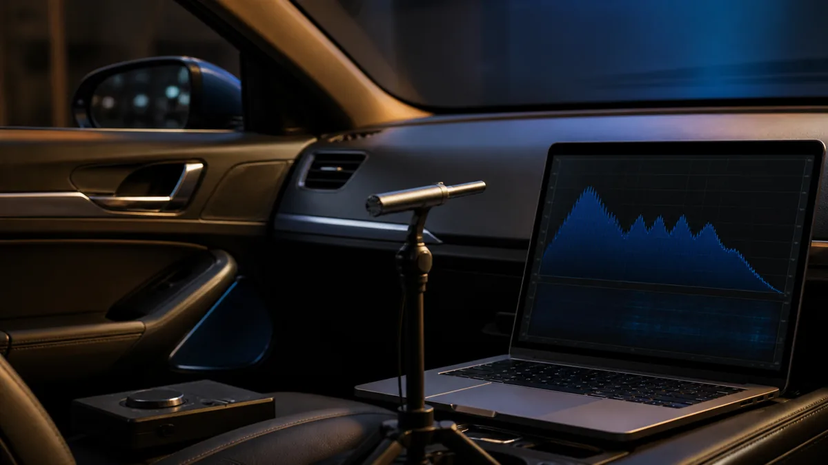
Car-audio tuning is the controlled adjustment of a known system toward a stated listening target. Measurement supplies observations; controls change the system. Confusing those roles leads to random settings and hard-to-reproduce results.
This page organizes the work. It is not a list of universal frequencies, delay values, or gain positions.
Controls and observations are different
| Item | Primary role | Can reveal or change | Cannot establish by itself |
|---|---|---|---|
| Level / input sensitivity | Control | Stage-to-stage operating level | That every upstream signal is clean |
| High-pass / low-pass filter | Control | Frequency range sent to a channel | Safe settings for an undocumented driver |
| Equalizer | Control | Level over selected frequency regions | The physical cause of every peak or dip |
| Polarity switch | Control | Connection orientation | Full phase relationship through frequency |
| Delay / time alignment | Control | Relative channel timing | One perfect result for every seat |
| RTA / spectrum display | Observation | Level by frequency band at a point or average | Complete time-domain behavior or audibility |
| Listening comparison | Observation | Perceived change for the listener and program | Electrical safety or an unseen fault |
The sequence matters because later controls cannot reliably repair an earlier fault. Equalization is not a substitute for correct routing, a healthy driver, a suitable acoustic installation, or a clean signal path.
Establish a baseline first
Before tuning, record the channel map, current settings, source behavior, listening positions, and measurement conditions. Verify that channels play the intended drivers and that obvious mechanical noise, intermittent connections, or protection events are absent.
Save a restorable configuration. If each experiment changes several controls, the result cannot identify which change helped.
Set operating relationships before tonal shaping
Input sensitivity, channel level, and source volume define how the signal moves through available headroom. The gain-versus-volume comparison explains the roles without supplying a model-independent calibration procedure.
Filters then limit channel bandwidth according to the actual drivers, locations, enclosure, and system plan. High-pass versus low-pass explains the vocabulary. The exact cutoff, slope, and protection requirement remain product- and system-dependent.
Resolve routing, polarity, delay, and crossover interaction
Polarity inversion and phase are related but not interchangeable. Delay changes arrival relationships; filters and acoustic paths also change phase through frequency. Read phase versus polarity before treating a polarity button as a universal phase fix.
Time alignment can move relative arrival relationships toward a chosen listening position, but a cabin has multiple paths and seats. Audiotec Fischer’s DSP tuning publication discusses time and phase behavior in the context of system tuning rather than as one isolated distance entry.
Measure before applying detailed EQ
An RTA can make frequency-level patterns visible. AudioControl’s DM-RTA manual documents frequency on the horizontal axis, level on the vertical axis, and selectable resolution and settling behavior. Those display choices affect what the operator sees.
KICKER’s RTA tuning paper provides a manufacturer workflow example. It should not be reduced to “make the graph flat”: microphone position, test signal, background noise, target response, seat averaging, and the limits of EQ all matter.
Use EQ for bounded response work
Graphic and parametric equalizers provide different adjustment structures. The graphic-versus-parametric EQ guide explains frequency, gain, and Q without giving a generic target curve.
A narrow cancellation caused by path interaction may not respond usefully to large boost. A peak observed at one microphone position may not exist at another. Measure after each meaningful change and compare more than one position when the goal covers more than one listener.
Finish with repeatable checks
The final record should include source and test-signal details, microphone and calibration information, vehicle state, seat and microphone positions, processor preset, measurement traces, and listening notes. Recheck at realistic operating levels and with varied program material.
Tuning is complete when the stated target is met within known tradeoffs—not when every control has been moved.
Last verified: August 23, 2026.
Sources
- KICKER, Properly Tuning a System with a Real Time Analyzer.
- AudioControl, DM-RTA Owner’s Manual.
- Audiotec Fischer, Sound Tuning Magazine: DSP Special Vol. 2.