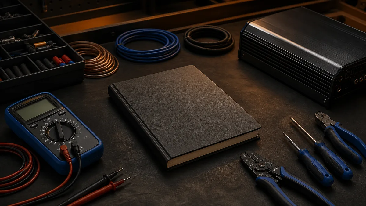
Car-audio wiring is not one task. It is a chain of decisions: understand the load, read the exact equipment requirements, protect the conductor, route the complete current path, preserve the signal path, and verify behavior under load.
This page is the map. It does not identify a vehicle wire or prescribe a conductor, fuse, ground point, or amplifier load.
Follow the dependency order
| Decision | Question it answers | Read next |
|---|---|---|
| Electrical model | How are voltage, current, resistance, and power related? | Electrical basics |
| Equipment boundary | What supply range, current protection, and load does this exact model require? | Current manufacturer manual |
| Complete current path | How do positive and return conductors participate? | Power wire vs ground wire |
| Fault protection | What is the fuse protecting, and where does the protected conductor begin? | Fuse placement and function |
| Conductor selection | Which inputs control an acceptable cable choice? | Power-wire gauge |
| Loaded verification | Is resistance in the operating circuit consuming voltage? | Voltage drop |
| Control and signal | What turns the amplifier on, and what carries audio? | Remote turn-on and signal path |
The order matters. A neat cable route cannot correct an invalid amplifier load, and a large conductor cannot replace correct overcurrent protection.
Start with the exact manuals
Manufacturer instructions are product-specific evidence. KICKER’s CXA amplifier manual, for example, defines model-dependent power/ground conductor and fuse requirements. Another product may use different terminals, protection, turn-on behavior, or operating limits.
Record the exact model and manual revision before buying or altering hardware. Do not infer requirements from the enclosure, connector shape, marketing wattage, or another model in the same brand.
Keep four paths distinct
An installation can contain several paths that interact but do different jobs:
- the high-current positive supply path;
- the return path through conductors and vehicle structure;
- the low-current control or remote-turn-on path;
- the audio signal path, which may be analog, digital, speaker-level, or line-level.
Confusing them leads to weak diagnosis. An amplifier power indicator does not prove that audio reaches its input, and a clean audio cable does not prove that the supply remains acceptable under load.
Verify under operating conditions
Fluke’s automotive electrical troubleshooting guidance explains why voltage-drop testing is performed while current flows. A connection can appear intact and show continuity while still causing a meaningful loss under load.
Measurements need context: vehicle state, source voltage, load condition, meter points, polarity, and product limits. An isolated number without those boundaries is not a diagnosis.
Separate universal relationships from variable choices
Ohm’s Law is established. A specific cable size, fuse family, ground location, remote trigger, or pass/fail voltage is variable. Those choices depend on equipment documentation, conductor construction, length, environment, routing, vehicle architecture, and applicable practice.
This separation is central to Car Audio Atlas: calculations can be checked deterministically, but installation suitability cannot be declared from arithmetic alone.
Stop conditions
Stop if you find battery damage, smoke, heat discoloration, melted insulation, loose high-current terminals, repeated fuse operation, exposed conductors, or an unknown safe isolation procedure. Never bypass a fuse or increase its rating to keep it from opening.
Hybrid, electric, start-stop, and computer-controlled charging systems require vehicle-specific service information. Use qualified automotive or installation support when that scope is unknown.
Last verified: August 23, 2026.