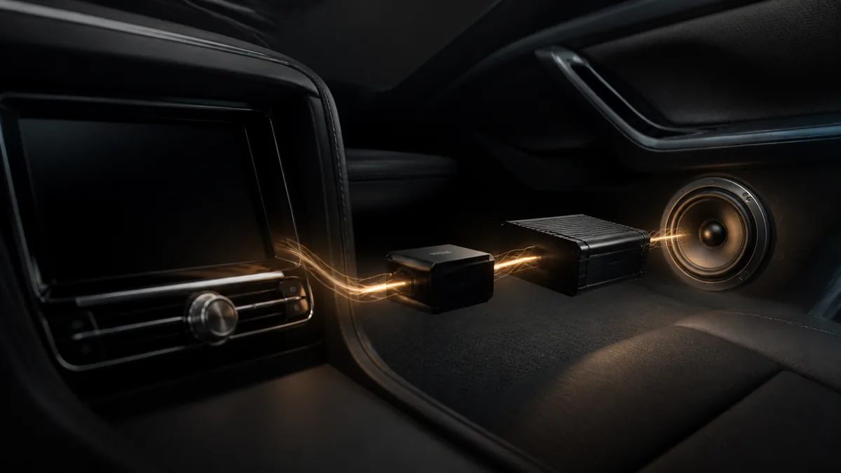
The signal path is the route taken by the audio information. It begins with recorded or received program material and ends when loudspeakers turn an amplified electrical waveform into sound.
It is not the route that battery current takes to power the equipment. A useful system drawing keeps the audio path and power path visually separate.
The five functional stages
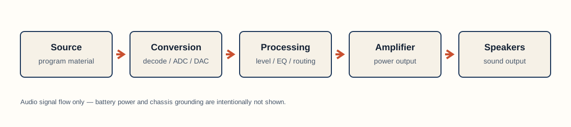
Most systems can be understood with five stages, even when several stages share one chassis.
1. Source
The source supplies the program: broadcast radio, a file on USB storage, a phone stream, or another media input. The source may already be digital, or it may arrive as an analog electrical signal.
“Digital source” does not mean every later connection stays digital. At some point a conventional loudspeaker needs an analog, power-amplified waveform. The system may convert formats before that point.
2. Decoding and conversion
Compressed audio must be decoded before playback. Digital samples may then pass through digital processing and a digital-to-analog converter (DAC). An analog input may pass through an analog-to-digital converter (ADC) if a DSP needs to process it numerically.
Analog Devices’ DSP introduction shows this general sequence: real-world analog input can be digitized, processed, and converted back to analog for a speaker system. The exact order depends on the product.
3. Control and processing
Volume control changes level. Balance and fader change the relationship among channels. Equalizers change level by frequency region. Crossovers attenuate selected frequency regions before signals reach different drivers. Delay can alter arrival timing.
These functions may exist in a receiver, factory amplifier, standalone DSP, or external amplifier. “No separate DSP box” does not prove that no digital processing occurs.
4. Power amplification
Signals used between source and processor stages are not normally intended to drive a loudspeaker directly. A power amplifier produces the higher-power output used by the driver.
An aftermarket system may carry a lower-level signal to an external amplifier through RCA connections, or it may feed a compatible higher-level input from factory speaker wiring. These are categories, not universal connection instructions. Input capability and limits come from the exact amplifier manual.
5. Loudspeaker output
Speaker wire carries the amplifier’s output to a loudspeaker or passive crossover network. The driver converts the changing electrical signal into diaphragm motion and acoustic pressure changes in the cabin.
The same path in three example systems
| System | Simplified signal path |
|---|---|
| Basic factory system | Factory source/control/amp → factory speakers |
| Aftermarket receiver only | Receiver source/processing/internal amp → speakers |
| Receiver, DSP, and external amplifiers | Receiver output → DSP → amplifiers → speakers and subwoofer |
These examples describe functions, not a promise about a particular vehicle. A premium factory system may have a separate networked amplifier, multiple processed outputs, microphones, and signals used for chimes or active noise control.
Signal level is part of the path
“Audio signal” is a broad description. A digital data link, a low-level analog output, a factory amplified speaker output, and an external amplifier’s speaker output are not interchangeable merely because all represent audio.
A component receiving a signal must support its:
- format: analog or a particular digital protocol;
- level range;
- channel count and assignment;
- reference or grounding arrangement;
- frequency content and any processing already applied.
That is why a line output converter or DSP can be more than a plug adapter. In some systems it must accept, combine, condition, or reinterpret factory outputs before another amplifier can use them. Crutchfield’s overview of factory-system DSP integration illustrates several possible positions for a processor, but vehicle-specific behavior remains variable.
How the signal path helps troubleshooting
Signal flow turns a vague complaint into a sequence of boundaries. If one source fails but another works, the common downstream stages are less likely to be the first place to investigate. If every source fails on one channel, the fault may be after the point where channels split. If an amplifier has input but no output, the problem boundary has moved again.
Those are reasoning patterns, not proof of a particular fault. Measurements, manuals, and safe access procedures are still required before touching wiring.
Common misconceptions
The head unit always powers every speaker. Not in systems with a separate factory or aftermarket amplifier.
RCA always means an unprocessed full-range signal. The connector shape does not prove level, bandwidth, or processing.
A DSP always sits between an aftermarket radio and amplifier. Processing may be built into other products, and factory integration can place it elsewhere.
The remote turn-on wire carries music. It is a control function, not an audio program channel.
Next concepts
The path becomes easier to read after learning what frequency describes, why decibels need a reference, and how analog and digital audio differ.
Last verified: August 22, 2026.
Sources
- Analog Devices, A Beginner’s Guide to Digital Signal Processing.
- Crutchfield, What does a digital signal processor do?.
- Crutchfield, Connecting your car speakers to an amp.