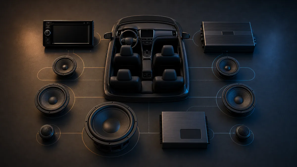
A coherent car-audio system starts with constraints and goals, not a shopping list. The useful question is not “Which parts are best?” but “Which complete signal, power, acoustic, and installation plan can meet this vehicle’s goal without asking any part to do an undocumented job?”
This hub maps those decisions. It does not prescribe wiring, fuse sizes, crossover points, or product combinations.
The planning sequence
| Decision | What must be known | What it constrains next |
|---|---|---|
| Define the use case | Listening positions, desired improvement, output priority, cargo and appearance limits | Speaker layout, subwoofer strategy, processing scope |
| Map the factory system | Source, channels, factory processing, amplifier, alerts and vehicle functions | Integration interface and usable input signals |
| Choose acoustic coverage | Driver roles, locations, enclosures and listening area | Channel count, filters, delay and required output |
| Build the signal plan | Analog/digital path, level type, routing and processing | DSP inputs/outputs and amplifier inputs |
| Build the load and power plan | Final nominal loads, continuous ratings and channel modes | Amplifier records and validated configurations |
| Check electrical and physical fit | Supply behavior, cable paths, ventilation, mounting and service access | Whether the plan is installable and maintainable |
| Define verification | Electrical checks, polarity, signal tests and acoustic measurements | Commissioning and tuning sequence |
The order is iterative. A space limitation can change the enclosure, which changes the acoustic target, which can change amplification and processing. A factory-system discovery can invalidate an assumed input before any product is purchased.
Start with an observable goal
“Better sound” is too vague to design against. A practical brief names the problem: missing low-frequency extension, poor front-stage localization, insufficient clean level, inconsistent response between seats, lost factory functions, or a system that cannot be serviced cleanly.
The brief should also name priorities that may conflict. Maximum cargo retention, high low-frequency output, concealed installation, several optimized seats, low cost, and minimal electrical demand cannot all be assumed at once.
Inventory the vehicle before selecting interfaces
Modern factory systems vary by year, trim, option package, software, amplifier, active-noise-control implementation, and warning-sound routing. Connector appearance does not establish signal type or channel content.
Document what is present and what must remain functional. The car-audio signal-path map explains the functional blocks; speaker-level versus line-level explains two common signal categories. Neither identifies a vehicle-specific wire.
Treat speakers and enclosures as acoustic decisions
Driver size and count are not a complete acoustic plan. Location, baffle behavior, enclosure loading, crossover region, listening geometry, and required output all matter. The subwoofer-enclosure map shows why “sealed” or “ported” is only the start of a design description.
For a subwoofer system, manufacturer enclosure data and the finished net airspace matter. KICKER’s box-building guide illustrates how panel thickness and internal displacements separate external dimensions from working volume.
Match records, not marketing labels
Compare continuous ratings at the actual nominal load and operating mode. CTA’s 12-volt amplifier standard overview explains why declared test conditions matter. “1,000 watts” without load, voltage, distortion, channel mode, and rating method is not enough information.
Use the bounded amplifier/subwoofer matching worksheet only after a validated final nominal load exists. It compares copied records; it cannot approve excursion, enclosure, filtering, thermal behavior, electrical supply, or installation quality.
Make measurement part of the design
A system is not complete when every box turns on. The commissioning plan should establish safe checks before acoustic tuning, then verify channel routing, polarity, noise, output behavior, and response at the intended seats.
Audiofrog’s A-Series manual is a useful primary example of product-specific level, filter, phase, and system-configuration guidance. Its procedures apply to the documented products and cannot be generalized into universal settings.
What belongs on the design record
Keep one concise system record containing:
- vehicle year, model, trim, and factory-audio option;
- goals, listening positions, constraints, and accepted tradeoffs;
- source-to-speaker channel map;
- exact product models and applicable manuals;
- nominal loads and continuous ratings with test conditions;
- enclosure assumptions and measured finished volume;
- cable, protection, mounting, ventilation, and service plan;
- baseline and final measurements;
- settings backup and change history.
That record prevents the system from becoming a collection of undocumented adjustments. It also makes later troubleshooting much faster.
Last verified: August 23, 2026.
Sources
- Consumer Technology Association, 12-Volt Amplifiers.
- Audiofrog, A-Series Amplifier Manual.
- KICKER, How to Build a Subwoofer Box.