
A DVC subwoofer has two voice coils, and each coil has its own positive and negative terminal. Connecting the two coils in series or parallel changes the nominal load presented by that driver; it does not change the coil’s own nominal rating.
Confirm the label before calculating
“DVC 4 Ω” normally means two nominal 4-ohm coils. It does not mean that both coils have already been combined into one 4-ohm load. Product markings and the manual must confirm the actual terminal layout and per-coil rating.
The KICKER CompVR manual also specifies that both coils should be connected. This guide does not treat an unused coil as a normal configuration.
Series voice-coil model
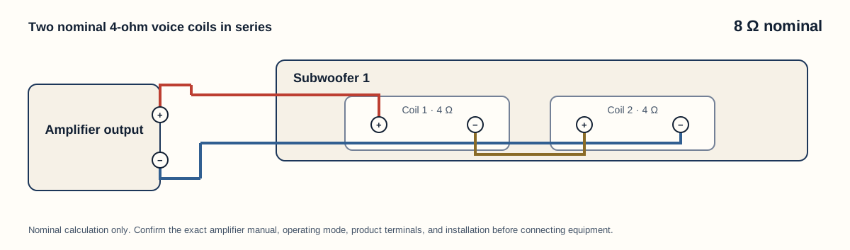
In a series path, current passes through one coil and then the other. For the nominal equal-load model, the coil impedances add.
The connection sequence documented by KICKER starts at amplifier positive, passes through the first coil, joins that coil’s negative terminal to the next coil’s positive terminal, and returns from the final negative terminal to amplifier negative. Polarity markings remain essential.
Parallel voice-coil model
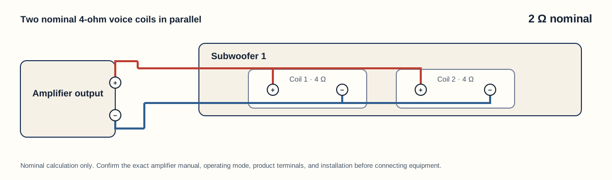
In a parallel path, the positive terminals share the amplifier-positive net and the negative terminals share the amplifier-negative net. For two equal nominal coils, the equivalent nominal result is one-half of one coil’s rating.
Manufacturer-confirmed single-driver examples
| DVC label, per coil | Coils in parallel | Coils in series |
|---|---|---|
| DVC 2 Ω | 1 Ω nominal | 4 Ω nominal |
| DVC 4 Ω | 2 Ω nominal | 8 Ω nominal |
These results appear in the cited KICKER manual. They describe nominal topology outcomes, not universal amplifier approval.
Multiple DVC subwoofers add another layer
With identical multiple DVC drivers, there are two decisions: how the coils within each driver are combined, and how the resulting drivers are combined. A balanced series-parallel system must use every coil, preserve polarity, and give equivalent treatment to identical drivers.
Use the subwoofer wiring calculator to enumerate the supported balanced layouts. It intentionally shows all calculated outcomes without marking the lowest load as recommended.
Checks required before any connection
- Confirm that every subwoofer is the same model and coil version.
- Confirm that the impedance marking is per coil rather than a selectable or prewired product value.
- Identify the terminals from the product manual—not from basket position or wire color alone.
- Compare the calculated nominal result with the amplifier manual for the exact output and operating mode.
- Stop if the system uses mixed drivers, an unfamiliar terminal board, multiple channels, bridging, or any condition outside the calculator scope.
Validation boundary
The equations, topology, terminal nets, and SVG output have deterministic tests. That establishes internal agreement. It does not verify an installer’s actual products, enclosure wiring, amplifier mode, conductors, or vehicle, so the page does not make a product-specific safety or compatibility decision.
Last verified: August 22, 2026.
Sources
- KICKER, Series, Parallel, and Series-Parallel Speaker Wiring.
- KICKER, CompVR Subwoofer Technical Manual.
- Rockford Fosgate, Dual Voice Coil Subwoofer Installation Manual.
- Crutchfield, Subwoofer Wiring Diagrams.