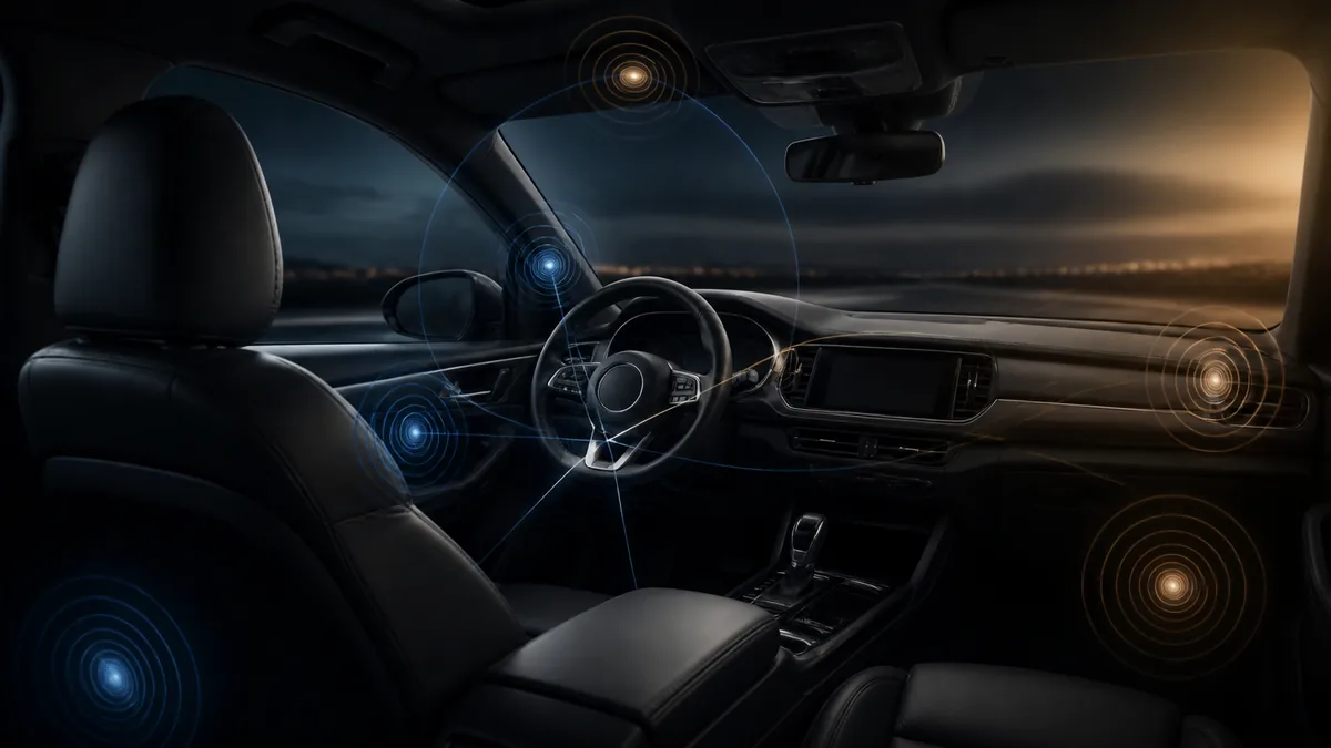
Time alignment in car audio uses delay to change when one channel’s output reaches a chosen listening position relative to other channels. It is useful because the driver usually sits much closer to some speakers than others.
Delay does not physically move a speaker, remove reflections, or produce one ideal result for every passenger.
What the control can and cannot do
| Time alignment can change | It does not independently correct |
|---|---|
| Relative channel arrival time | Unequal frequency response |
| Arrival relationship through a crossover region | Wrong polarity or channel routing |
| Apparent image position for a selected seat | A rattling panel or damaged driver |
| The timing contribution of a subwoofer relative to the front stage | Factory processing that has not been characterized |
| Tradeoffs among listening positions | Every reflection and acoustic path in the cabin |
Eclipse’s audio adjustment manual shows a manufacturer implementation that accepts speaker-distance information and applies timing correction. It demonstrates the concept, but its units, limits, channel model, and procedure belong to that product.
Why the near speaker is usually delayed
Sound from a nearby speaker has a shorter direct path to the listener than sound from a farther speaker. A processor can hold back the nearer channel so selected arrivals occur closer together in time.
This can improve image placement and crossover integration at the reference seat. The underlying control is delay, even when an interface asks for distance and converts it internally.
Distance is an estimate, not the finished proof
A tape measure usually measures from a visible point on the speaker to a chosen point near the listener. Actual acoustic behavior also includes the driver’s acoustic center, filters, enclosure, placement, reflections, factory processing, and frequency-dependent paths.
Distance entry is therefore a reasonable starting state when the manual supports it. Measurement and controlled listening determine whether the implemented result meets the goal.
One delay has different phase effects by frequency
Time is fixed; phase angle is frequency-dependent. A delay that changes a crossover relationship at one frequency does not represent the same phase angle everywhere else.
That relationship is why phase and polarity must remain distinct. A polarity inversion is not a substitute for arbitrary delay, and a delay value does not establish correct polarity.
Driver-only and multi-seat goals conflict
A delay arrangement optimized at the driver’s head is measured from one geometric location. The passenger occupies another. Moving the reference position changes path differences, so a single preset cannot make both seats geometrically identical.
Possible design choices include a driver-priority preset, a broader compromise, or separate presets if the processor supports them. Audiotec Fischer’s DSP tuning material treats time and phase as interacting tuning variables rather than promising one universal seat solution.
A bounded workflow
- Confirm the channel map, polarity, and filters.
- Choose and document the reference seat and microphone/listening position.
- Measure physical paths only as the processor manual directs.
- Save the baseline before applying delay.
- Compare repeatable measurements through relevant crossover regions.
- Confirm the perceptual result with controlled listening.
- Recheck other seats included in the project goal.
An RTA alone shows frequency-level information; it may be part of a process, but it does not expose all timing behavior. KICKER’s RTA paper is an example of a broader measurement workflow, not evidence that one graph validates every delay.
Scope boundary
This article explains the function and tradeoffs. It intentionally gives no universal milliseconds, centimeters, acoustic-center offset, or “perfect” DSP value. Apply only the exact controls and limits documented for the installed processor, and preserve a restorable configuration.
Last verified: August 23, 2026.
Sources
- Eclipse, CD8445E Audio Adjustment Manual.
- Audiotec Fischer, Sound Tuning Magazine: DSP Special Vol. 2.
- KICKER, Properly Tuning a System with a Real Time Analyzer.